Integration and Test Process
When integrated, ACE becomes a critical part of your unmanned aircraft control system. It must be integrated, configured, and tested thoroughly. Refer to the ACE Component Specifications for details on the individual components.
Aircraft Autopilot Tuning
Before installing ACE, the UAV should be well-tuned and tested. It should be capable of stable flight across the full range of operating conditions.
Aircraft Components
Integration and testing of ACE into the aircraft requires the steps listed below.
ACE provides integration flexibility. The camera and computer can be mounted in different locations based on aircraft and payload needs.
Planck provides customers with detailed integration guides and interface control documents (ICDs) to assist with this process. Planck can also provided engineering and test support as needed.
Computer Mounting
The computer can be mounted within our outside of the aircraft using 4 mounting holes. The computer should be mounted within 300mm of the autopilot and 300mm of the camera, although these can be extended if care is taken to minimize interference. The computer requires a power input, a serial connection the autopilot, and a ribbon cable to the camera. In some configurations, an Ethernet port may also be used.
Note that the computer is not provided within an enclosure and should be protected from any water/rain that may be encountered during a mission.
Camera
The camera must be mounted rigidly in a fixed downward-facing vertical position using the 4 mounting holes. It requires an unobstructed view below the aircraft. Ideally, the camera is mounted within 50 cm of the aircraft's center of gravity and within 300 mm of the computer. The camera is connected to the computer with a ribbon cable and does not require additional power. For aircraft with high vibration levels, the camera may be mounted on vibration isolators.
Note that the camera is not provided within an enclosure and should be protected from any water/rain that may be encountered during a mission. Typically, this is done by mounting the camera within the fuselage and providing a small 1cm hole for the camera sensor.
Autopilot Firmware
For autopilots with ArduPilot firmware, Planck provides open-source custom firmware to enable ACE modes and telemetry. This should be installed on the autopilot. All existing ArduPilot functionality remains unchanged.
For other autopilots, including proprietary flight controllers, contact us to discuss interface and integration options.
Configuration
The system must be configured for each specific aircraft type. ACE includes a browser-based interface (Web UI) to easily access and adjust the configuration parameters. Most ACE parameters can also be modified via the MAVLink parameter protocol.
The autopilot firmware must also be configured to interface with ACE so that data can be passed between the two subsystems. This can be done with any compatible ground control software. Planck provides a specialized version of QGroundControl which supports the additional ACE-specific flight modes, failsafes, and mission items as well as offers feedback to the user about the state of the ACE system.
Calibration
ACE requires a one-time calibration process for each aircraft type to ensure the camera is installed and adjusted properly. This calibration is in addition to any normal calibration and tuning required on your aircraft. Planck provides calibration instructions to customers. This calibration does not need to be repeated for subsequent integrations onto the same aircraft type.
Ground Components
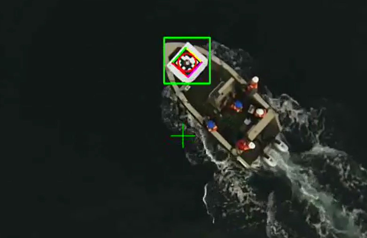
Landing target
The landing target designates the landing site for the aircraft. It can be mounted on any suitable landing location. It is recommend to attach it to a surface or structure if your aircraft generates enough downward prop wash that could blow the target away. Some customers may elect to permanently attach it to a structure using bolts, while others temporarily attach it using clips or adhesive. For testing purposes, the landing target may be laid on the ground.
GPS Receiver
A GPS receiver must be placed within 3 meters of the landing target. This receiver provides the position of the landing target to the aircraft during some flight modes that require it. The GPS receiver must be plugged into the ground control station so that it can be routed to the aircraft. The ACE system includes a GPS receiver for this purpose. The GPS receiver is not required for GPS-denied (e.g. tethered) operations.
Ground Control Software
Planck provides an open-source custom version of QGroundControl which can be used either as a reference design or for functional missions. If using different ground control software, it must be modified to enable ACE flight modes.
Testing
Testing is critically important prior to deploying any unmanned aircraft system. After the initial integration and configuration process is complete, Planck recommends the following testing regimes to gradually increase flight complexity without sacrificing safety.
Fly in an indoor safety cage (if possible) with a RC pilot backup
Fly from stationary locations at an outdoor test site with an RC pilot backup
Fly from a moving platform in controlled conditions with an RC pilot backup
Fly in a representative operational environment with RC pilot backup
Support
Planck can provide engineering support for the installation, configuration, and calibration process. Planck can also provide testing support, including indoor and outdoor flight testing.
Engineering support can be either remote (via video conference, phone, and email) or in person, depending on location and availability.
Planck also provides engineering services for ACE customization and general UAV autonomy and controls development.
Contact us for more information about engineering support options.
Last updated